|
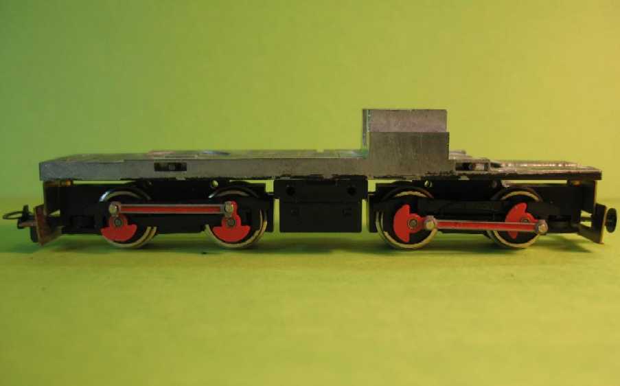
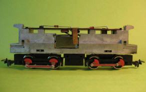
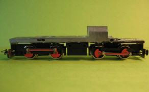
The chassis of the Liliput 2095 as out-of-the-box.
|
|
|
|
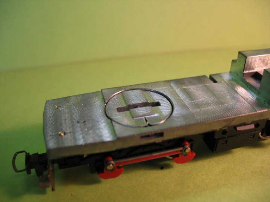
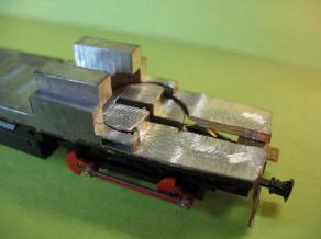
The diecast block of the chassis was milled down.
Motor, gears and electrics were removed completely.
The engine shall run freely, therefore even the collecting wipers have been removed. The camera is supplied with (rechargeable) battery power, illumination was dispensed with.
LED frontlights (power supply by the camera battery) might be well appealing for footplate rides at night ... DCC operating modellers may realize working LED headlights with power supply by well adjusted wipers on the wheels. Anyway, the rolling resistance of this quite heavy engine must not be underestimated!
|
|
|
Top of Page
|
Homepage English
|
|
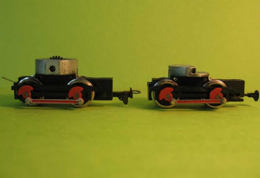
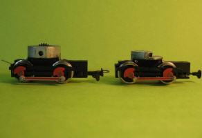
Original bogie (left) and the leading one reduced to fit under the camera.
The rear bogie was also reduced in height to a minimum (illustrated further below), to give as much space as possible for the battery above.
|
|
|
|
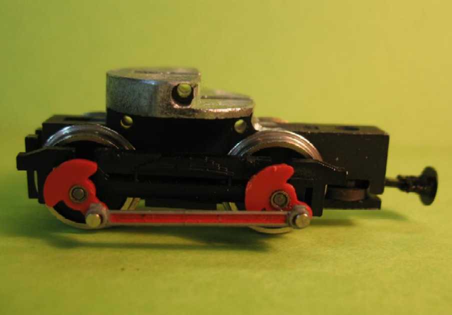
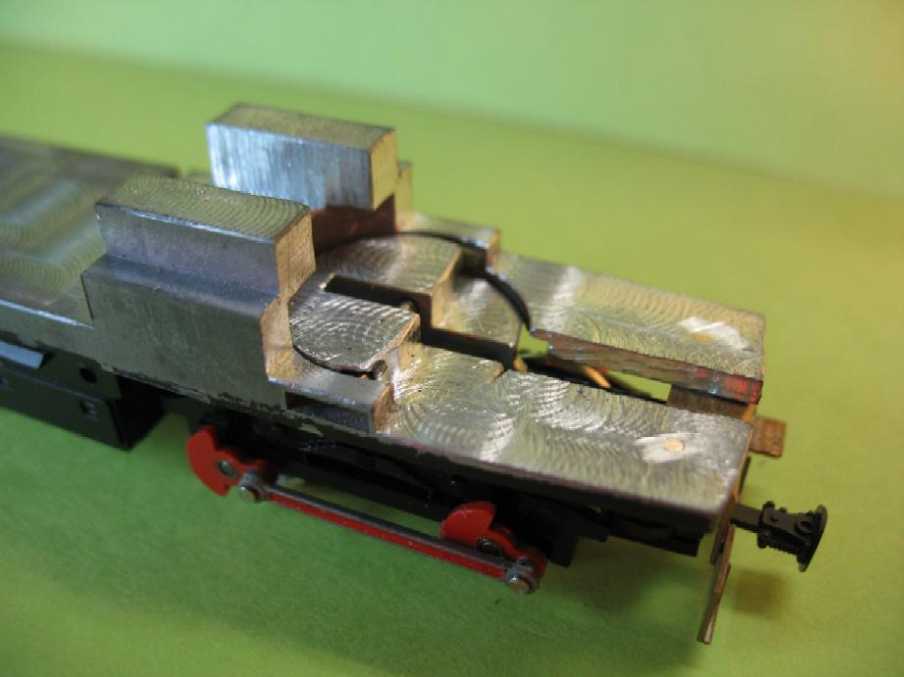
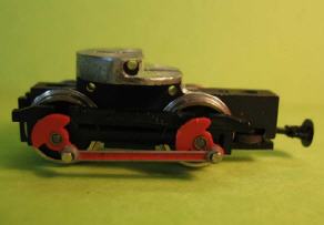
Another detailed view of the front bogie.
It is clearly visible that the bogie shaft (without gearwheel, but still necessary for guidance of the bogie) has just enough solid material around it.
|
|
|
Top of Page
|
Homepage English
|
|
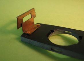
To improve the appearance of the engine, the characteristic front aprons have been made from brass sheet.
The whole leaves enough clearance for the original Liliput coupler or a more realistic one made from a BEMO buffer coupling.
|
|
|
|
|
The milled seat for the camera, with the fitted and likewise reduced bogie.
|
|
|
Top of Page
|
Homepage English
|

|
Rear bogie, with maximal height reduction.
|
|
|
|
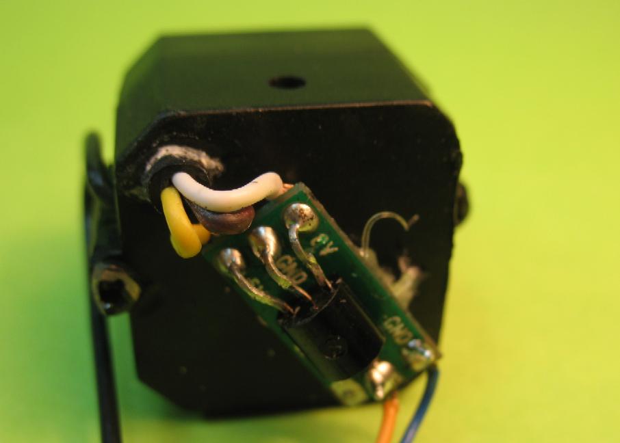
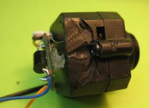
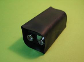
The camera.
Original power supply of the camera is provided via a cable and mulitpoint connector, alternatively to a mains adapter or to a 9V battery.
CAUTION! The camera's connector contains a small circuit to reduce the supply from 9 Volts to about 5 Volts. This circuit has been extracted carefully with a sharp knife and connected directly to the camera. The whole connector was too bulky to be retained.
|

|
|
Top of Page
|
Homepage English
|
|
Even the micro casing of the camera had to be further reduced, to provide enough clearance for the bogie underneath.
The camera is fixed with doublesided tape. It has to be adjusted exactly according to the aperture in the egine's body shell (see below). Inclination has to be found by visual control on the track to provide a suitable range. The lens can be focussed by twisting. A sufficiently sharp picture range can thus be obtained from approx. 6" in front of the engine to the far distance. After successful adjustment the camera's position can be secured with small blobs of hotmelt adhesive.
|
|
|
|
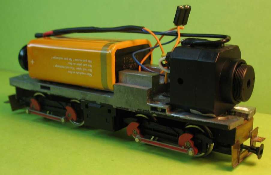
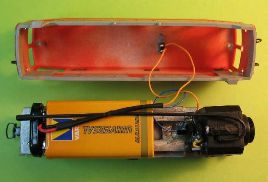
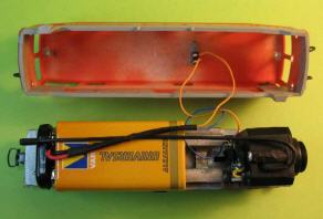
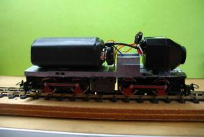
View of the engine with camera (right) and battery.
Unfortunately the usual 9 Volts battery blocks are about 2 mm too wide for the Liliput body. The tinplate housing of the battery can be carefully squeezed to measure in a vice until it fits snugly into the engine body.
|

|
|
Top of Page
|
Homepage English
|
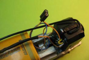
A micro connector has been soldered into the feed cable. This connects to an inobstrusive micro switch attached to the roof of the engine, to allow switching off the camera.
On top the camera's aerial is visible. This is still the long aerial of the initially installed 1,2 GHz camera, which however didn't apply to German legislation, which allows only devices in the 2,4 GHz range. This camera has been replaced in the meantime (see photos further below). The new camera has an aerial only just over an inch long.
|
|
|
|
|
|
The micro switch installed into the roof of the engine. It will be painted in the same colour as the roof, and will then be almost invisible.
This allows to switch off the camera at any time (saving energy), even without taking the engine off the tracks.
|
|
Top of Page
|
Homepage English
|
|
Connection from the chassis with the camera to the switch in the body's roof.
|
|
|
|
|

|
Underneath the windows the body shell received a 3mm-hole for the camera lens, which is placed exactly behind it. This tiny drilling is fully adequate! After painting of the engine the hole will be hardly visible anymore.
|
|
Top of Page
|
Homepage English
|
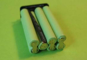
Th problem of the slightly oversized batteries can not be solved as described above with rechargeable batteries, as they have a plastic housing which doesn't tolerate the previously recommended "vice treatment".
The housing is removed (sharp knife) and the seven cells separated from each other to rearrange them in a new (and narrower) order.
|
|
|
|
|
|
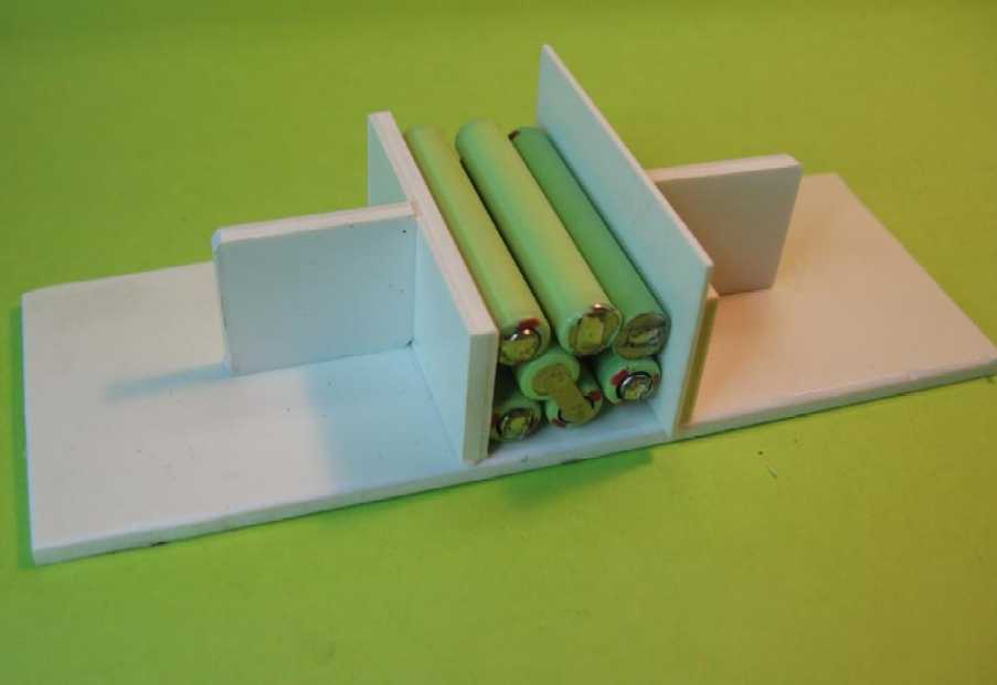
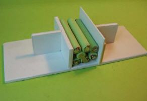
A case has been built from plasticard to assist the rearrangement of the cells to the new maximum width. They are fixed to each other with superglue.
|
|
Top of Page
|
Homepage English
|
|
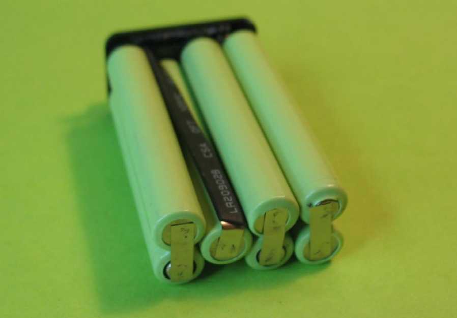
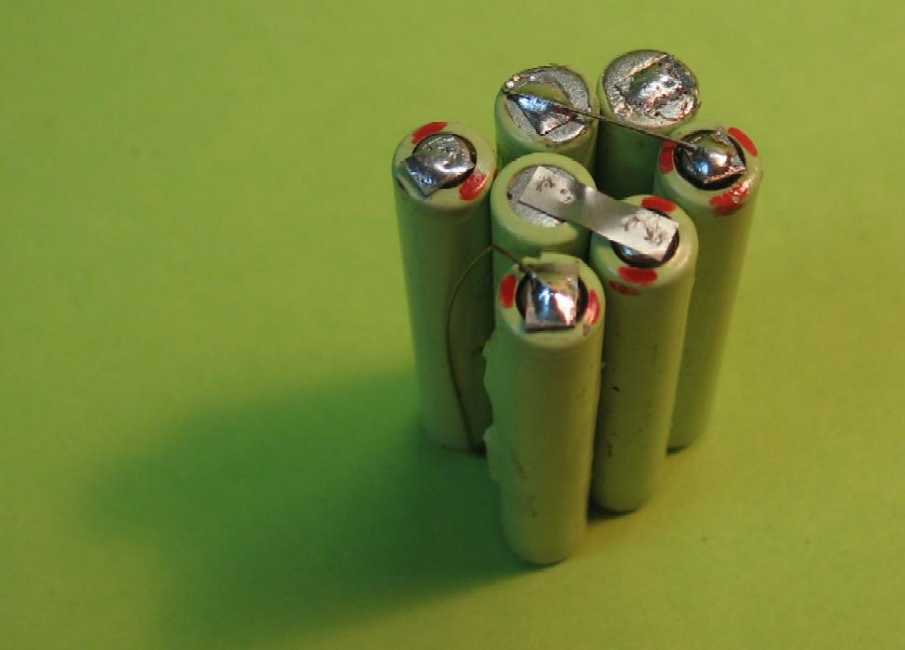
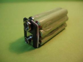
This is the interior of the new rechargeable battery block. The elements are already connected electrically. They can be soldered carefully with copper wire. All seven cells are connected serially - care for the correct polarity and arrangement of the individual cells to avoid hay-wire circuit.
|

|
|
|
|
|
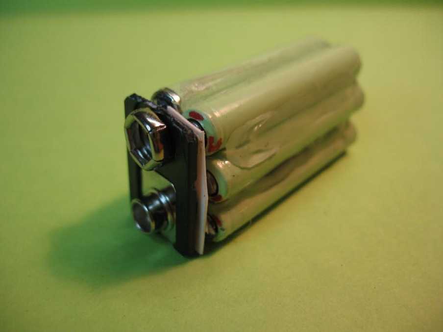
For connection the original top with its terminals is reused. It allows for easy exchange of the battery and above all provides connection to the battery charger.
|
|
Top of Page
|
Homepage English
|
|
The new block is covered with heat shrink tube. Here to be seen before heating.
|
|
|
|
|
|
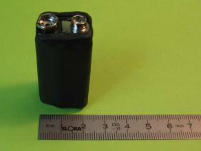
The finished "new" battery block. If high-grade NiMH batteries with a capacity of 250 mAh are used, this will suffice for 3 to 4 hrs operation.
|
|
Top of Page
|
Homepage English
|
This is the battery arrangement in the engine. The increased height of the new energy pack is not critical.
The engine body should be easily removable for battery change. Snap tabs should be reduced accordingly.
|
|
|
|
|

|
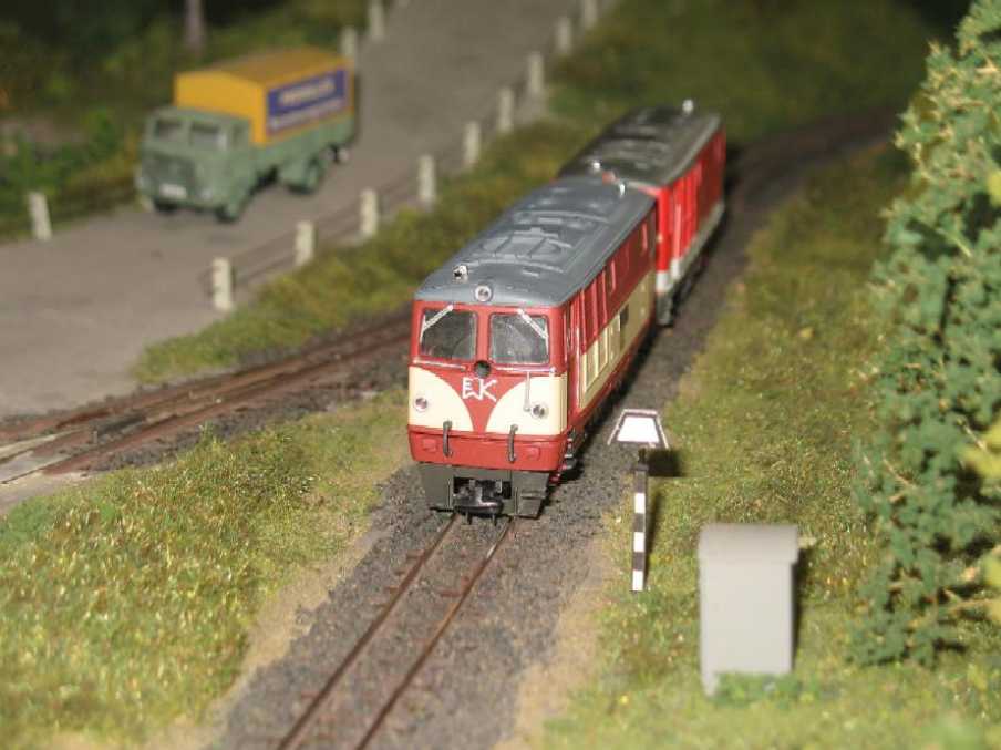
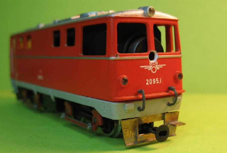
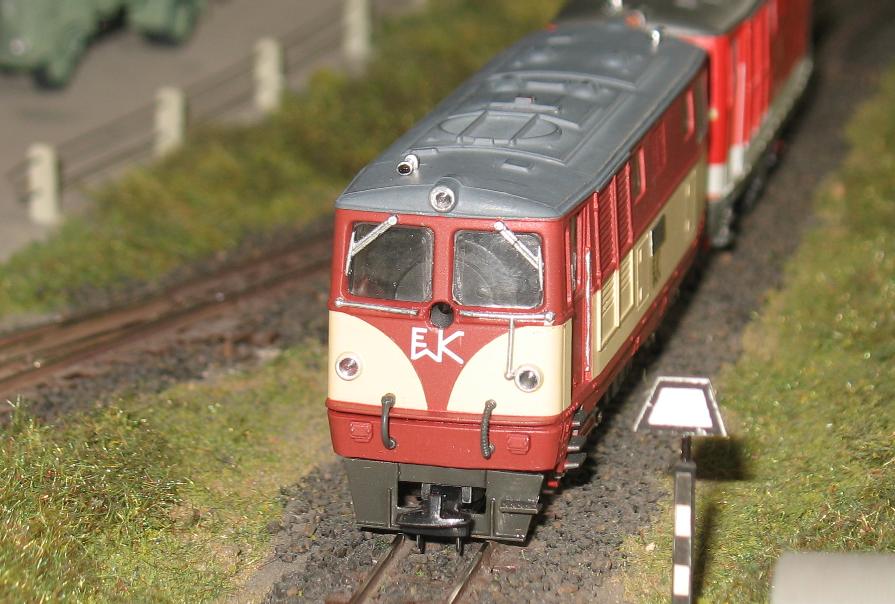
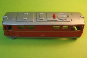
The new face of the engine after installation of the camera.
Spectators at a model exhibition, who first saw the TV picture on the screen, had some dificulties to identify the engine on the large modular layout. This is evidence for the unobstrusiveness of the engine's eye!
|
|
|
|
|
A short videoclip of a "footplate ride" on this engine is in preparation.
|
Please watch this site!
|
|
Top of Page
|
Homepage English
|